Subject : Front Suspension — 4×4 wheel hub Installation Procedure
Models : 2001 Ford F-Super Duty 250-550, Ford Excursion, Ford F-53 Motorhome Chassis
All vehicles
1. NOTE: Any time the wheel hub is eliminated for any cause, a new O-ring seal have to be installed. Failure to do so may cause a vacuum leak and lack of 4 wheel drive operations. Install a brand new O-ring.
2. NOTE: Position the hub in a comfortable-jawed vise. Install two nuts on the studs and use the outer nut to install the studs.
Vehicles equipped with ABS
3. Position the ABS sensor and install the bolt.
All vehicles
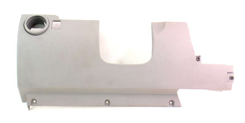
4. Place the brake disc shield.
5. NOTE: Apply a coat of Ford Excessive Temperature 4×4 Front Axle and Wheel Bearing Grease E8TZ-19590-A meeting Ford specification ESA-M1C198-A to the O-ring area of the wheel hub and bearing before putting in the hub and bearing. Install the wheel hub and bearing. a. Position the wheel hub and bearing. b. Install the 4 lock nuts.
Vehicles equipped with ABS
6. NOTE: The next step applies only to automobiles geared up with ABS. Join the ABS sensor harness. a. Place the ABS sensor harness and install the routing clips. b. Join the harness connector.
All vehicles
7. n-metallic thrust washer should be put in between the two steel thrust washers. Failure to take action will trigger extreme put on to the non-metallic thrust washer, allowing the axle shaft to travel additional in and out during torque thrust causing harm to the wheel hub and bearing, the axle shaft end seal and the axle shaft. Set up the snap ring. a. Position the three thrust washers onto the axle shaft. b. Set up the snap ring.
8. NOTE: Any time the hub lock is removed, a new O-ring seal should be installed. Failure to do so could cause a vacuum leak and loss of 4 wheel drive functions. Install a brand new O-ring.
9. Install the hub lock. a. Position the hub lock. b. Install the retainer ring.
10. Position the entrance disc brake rotor (1125) to the wheel hub (1104). Ensure that the wheel hub and the entrance disc brake rotor braking and mounting surfaces are clean. Use brake components cleaner to scrub the front disc brake rotor. 11. NOTE: Carry out this step for DRW vehicles only. Set up the entrance wheel hub extender and nuts.
12. NOTE: Caliper is removed for clarity. Position again the front disc brake caliper and anchor plate (2B292). a. Position back the entrance disc brake caliper and anchor plate bolts. b. Set up the front disc brake caliper anchor plate bolts.
13. Install the wheel and tire assembly. Check the system for regular operation.